
Assembling the Odroid Go.
Related : After assembling the Odroid Go, read the firmware upgrade guide
In celebration of their 10 year anniversary, HardKernel has released the Odroid Go, a $34 USD, Open Hardware, pocket-sized gaming device.
The Odroid Go has as its brain an ESP32 microprocessor. This microprocessor is well supported by the Arduino platform, which means you can program it with your own games and software.
Out of the box, the Odroid Go comes with emulators for the Nintendo Entertainment System, Gameboy, Gameboy Color, Sega Master System, and Game Gear video game platforms.
Tools needed
- Small Phillips screwdriver
- Micro SD Card
- Micro SD Card reader
- USB charger
- Computer
Optional
- Air blaster or compressed air can
Unboxing
Inside the box you will find the following components:


- One mainboard
- One rechargeable battery
- One LCD
- One Micro USB cable
- One Speaker
- One set of header pins
- A bag containing 10 screws
- Screen bezel
- One plastic buttons set (Directional pad, two buttons, and a power switch)
- 5 pieces of rubber button pads
- Two pieces of a clear plastic enclosure
Assembly
LCD
Remove the protective film but do not discard it yet. With the ribbon cable to your right, place the bottom of the LCD inside the two plastic tabs and press on the top of the LCD to snap it into place. If the LCD doesn’t snap in all the four holding tabs, don’t force it. Remove the LCD and try again. You can also try placing the LCD inside the top tabs and pushing on the bottom of it.

LCD firmly in place
With the LCD in place, take the protective film and place it once again on the LCD. This is to have the option to remove the LCD if a mistake is made at some point of the assembly.

Buttons
The next step is to but the buttons in the enclosure. Place the directional pad using the small indentation as a position guide. Then put the rubber conductor on top of it. To the same things for the A and B buttons. Place the reset and volume rubber pads. Finally, place the Select and Start rubber pads.


Mainboard
Place the mainboard, face down (with the words “10th Anniversary ODROID” facing you) on top of the front enclosure. Align the screw holes of the mainboard with the screw posts of the enclosure.


Using a small Phillips screwdriver, tighten the 4 screws shown with a white screw image on the mainboard.
LCD connector
To connect the LCD, open the LCD connector lock.

Next carefully bend the LCD ribbon cable until it slides in the LCD connector.

While holding the LCD ribbon cable in this position, engage the LCD connector lock. Push the LCD connector lock at both sided at the same time. The LCD ribbon has a white line printed that runs perpendicular to it. Make sure this line is aligned with the LCD connector on the mainboard.

Speaker
Take the speaker and connect it to the speaker connector on the mainboard. The speaker connector is keyed and will only connect if aligned the right way.

Place the speaker on the enclosure and coil the excess cable to allow the back face of the enclosure the close properly.

Battery
Like the speaker, the battery’s connector is keyed and will only connect if properly aligned. Once connected, place the battery in the space provided and in the orientation shown below.

Testing
While holding the battery and speaker turn on the unit to make sure everything is being assembled correctly.

A small red SD card icon should appear, indicating that no SD card is plugged in and no content is available to boot up. If no image appears, check the connection of the LCD ribbon cable. If the ribbon cable is connected properly, make sure that the battery is also well connected and that it has some charge in it.
Power switch
Before closing the unit, place the power switch cover. If it doesn’t snap into place with the switch in the “OFF” position, put the switch in the “ON” position and try again.

Closing the unit

Place the back cover and make sure that the screw holes are properly aligned.


Use a small Phillips screwdriver to tighten the enclosure. Do not over tighten the screws of the plastic posts will crack and you will need to order a new enclosure.

LCD bezel
Remove the protective film from the LCD.

The bezel is held in place using an adhesive and once placed, it will be difficult to remove. Take this opportunity to clean the LCD. Use a fine cloth to remove any fingerprint or smudge. Use an air blaster to remove any remaining lint.

Remove the adhesive cover from the bezel.

As well as the protective film from the center area.

Align the bezel and hold it in place using a bit of force for a few seconds to ensure the best adhesion.

The bezel also has a thin protective film. You can leave this film for some extra protection or remove it to obtain a crisper, brighter image from the LCD.

SD card setup
Place the SD card in the SD card reader and into the computer. Format the SD card using the FAT filesystem. Next, download the base file and uncompress it at the root directory of the SD card. Finally, download the ROM images for the games you own and place them in the respective console folder inside the roms folder of the SD card.
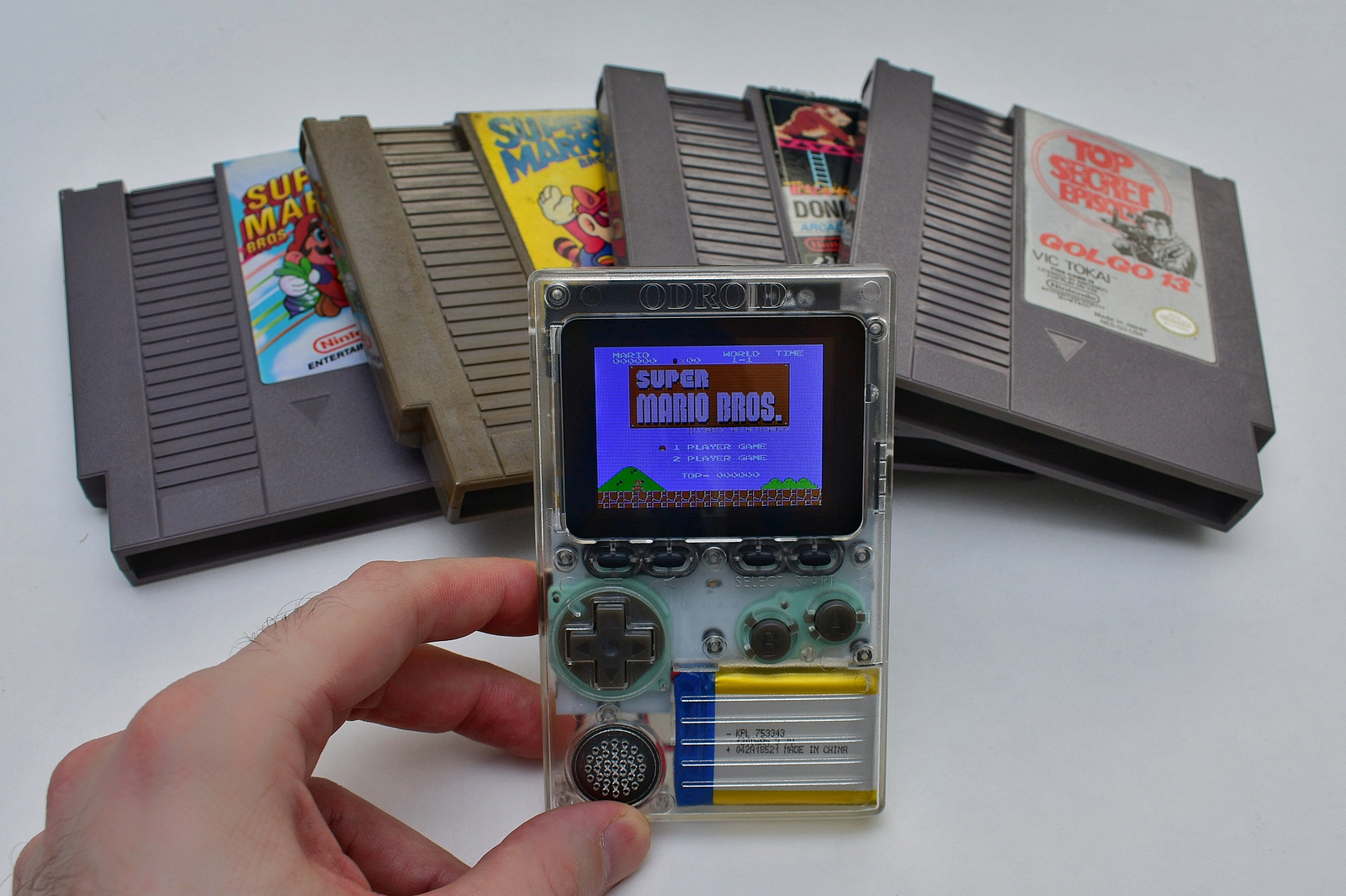
You are finished! You can now enjoy your games on the go without having to carry big clunky cartridges!
Conclusion
HardKernel has once again outdone themselves with a fantastic product. Portable emulation using a dual core ESP32, a 2.4 inch color LCD, amplified audio, a 1.2Ah lithium battery with battery management. The Odroid Go is hackable open hardware with schematics and free software repositories (even a Doom port!). It has a header providing I2C, SPI, and GPIO connectivity. And all this for $34 USD!