
Adding a remote serial console to an ODROID C2
In a previous post I mentioned that I used an ESP8266 as a WiFi to serial console bridge. Having a secondary method to connect to a headless computer is a functionality that is very common when it comes to commercial servers. When working with servers and network equipment unexpected situations will make it necessary to have the means to continue managing, power cycling or even reinstalling software in the equipment remotely. The most complete solutions implement out-of-band management which provides access to the equipment via a dedicate communication medium. The WiFi to serial console bridge in this post falls under the in-band management classification. This is because it uses the same medium for management as the computer uses for normal communications, requires support on the part of the computer to work, and requires the computer to be powered on.

Basic tools and materials needed
Materials
To build this WiFi to serial console bridge you will need:
- An ESP8266 board. I used an ESP-01 as it was the most easy to source at the time and one of the smaller modules available for this microcontroller.
- Wire cutters
- Wire strippers
- Solder iron
- Solder wire
- 4 wire connector set
- 3 x 10k ohm resistors
- ODROID C2

An ESP8266 in an ESP-01 module configuration. Image from https://en.wikipedia.org/wiki/ESP8266
The ESP8266 is a low cost microcontroller with a full TCP/IP stack and wireless capabilities. It is manufactured by Espressif Systems and has become very popular.
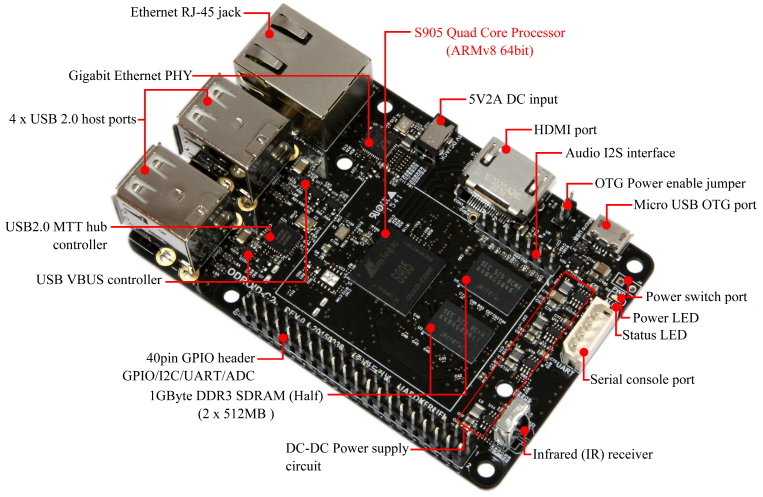

Since the ESP8266 and the ODROID C2 use 3.3 volt logic they can be connected directly to each other. Images from: http://www.hardkernel.com/main/products/prdt_info.php?g_code=G145457216438&tab_idx=2 and https://en.wikipedia.org/wiki/ESP8266
The firmware
The first step is to program the ESP-01 with the firmware that will provide an terminal in a web site over WiFi. Original I built my own firmware but since have found the espterm-firmware. This firmware emulates a DEC VT-100terminal inside a webpage over WiFi.
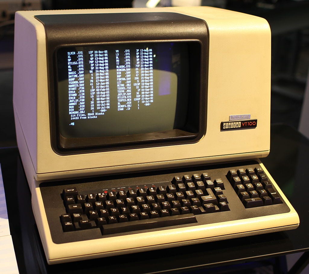
This is what your ODROID C2 thinks is connected to when using espterm. Image from https://en.wikipedia.org/wiki/VT100
Since the ESP-01 provides just the bare minimum hardware, to burn the espterm firmware you need an ESP-01 programmer. This is needed to place the ESP-01 in “flash mode” so that it accepts new firmware code, otherwise it boots in “run mode” and will only execute what’s already in its flash memory. You can purchase one or you can build your own with a few parts.
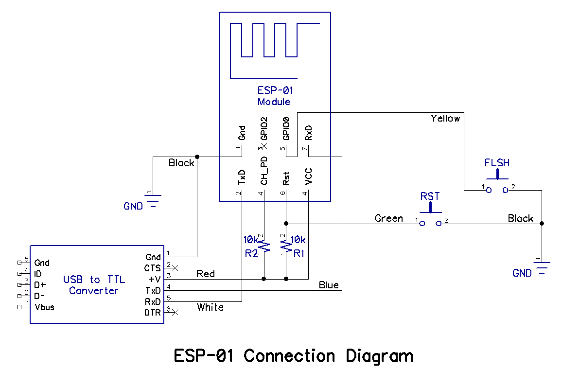
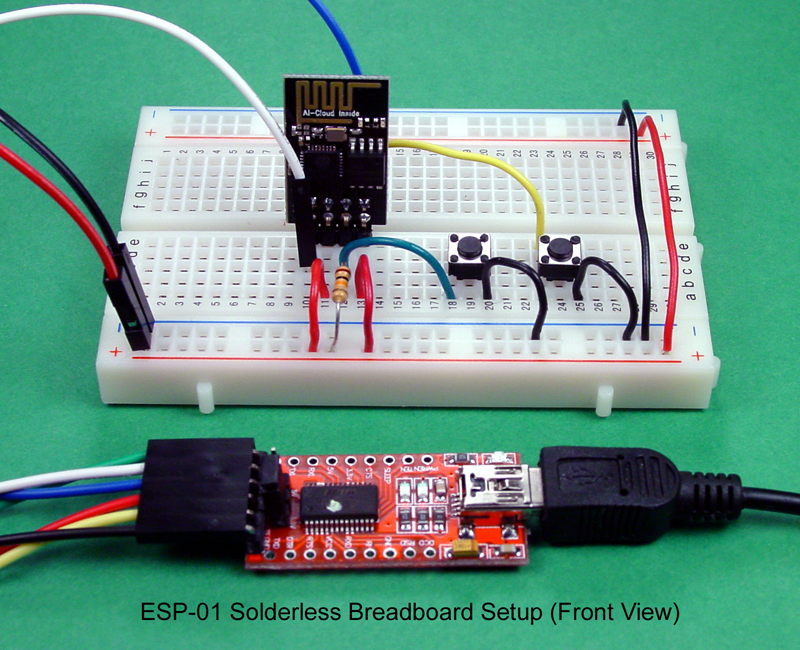

A breadboard ESP-01 programmer from http://ai-thinker.blogspot.com/2016/03/breadboard-and-program-esp-01-circuit.html and a commercial one from https://www.aliexpress.com/item/ESP8266-Wi-Fi-Transceiver-Module-USB-to-ESP-01-Adatper-Serial-Wireless-Adapter-Debugging-Firmware-Programming/32765537900.html
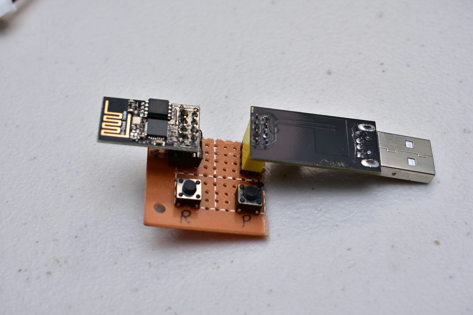
My MacGyver ESP-01 programmer with Program and Reset buttons.
To flash the firmware to the ESP-01, espterm recommends using the free open source esptool tool.
Download the latest version of espterm from the releases page and uncompress it. Among the uncompressed files there will be one called flash.sh that will call esptool with the required arguments to burn the firmware to the ESP-01.

espterm version 2.3.1 English uncompressed
Cabling
The ODROID C2 uses Molex 5268-04 connector for the serial console. I have not been able to source this connector so I remove it and use another easier to find, 4 pin, keyed connector.

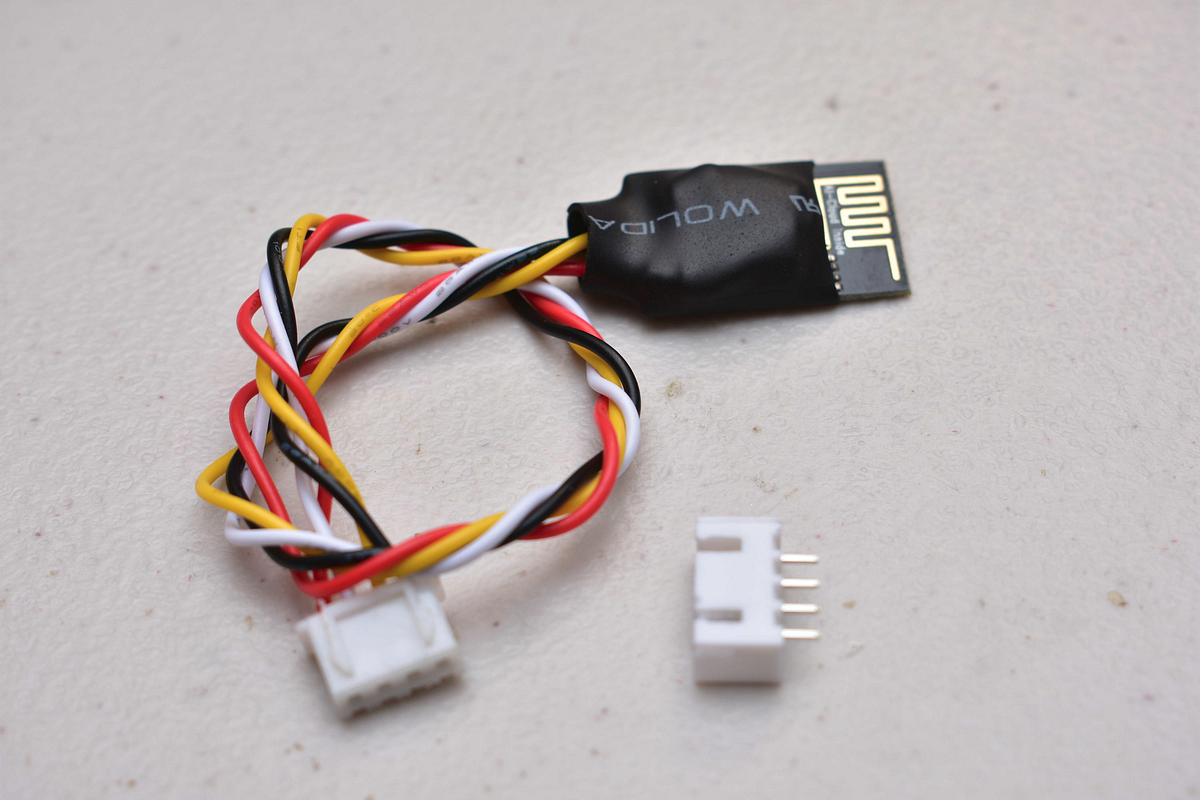
Molex 5268 connector removed and replaced with a JST 4 pin connector.


I like to re-arrange the pins by colors so they more closely represent their use. Red for Vcc, black for ground, yellow and white for data.


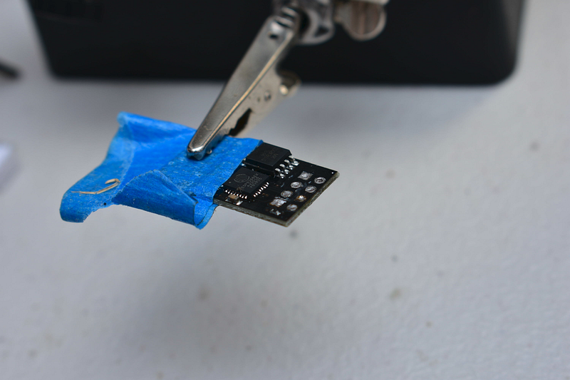
Next the pins are desoldered and the pads cleaned.


The connector cables are now soldered matching the pin layout of the ODROID C2’s serial console pinout inverting transmit and receive lines (TX, RX). ESP Vcc to C2 Vcc, ESP GND to C2 GND, ESP TX to C2 RXD and ESP RX to C2 TXD.

10K ohm pull up resistors are connected to the CH_PD , RST and GPIO0 pins. This makes sure the ESP-01 always boots up in “run mode” and reduce the chance of any electric noise causing instability problems.

The resistors are enclosed in heat shrink tubing and then the entire ESP-01 is enclosed in heat shrink tubing too.


The ESP-01 connected to the serial console and tucked between the USB ports.
Connectivity
By default the espterm boots up in passwordless access point mode with an SSID of “TERM” plus a random number sequence. It also enables its own DHCP server. In this mode only computers with a WiFi card will be able to connect to it.


Access point configuration screens of espterm.
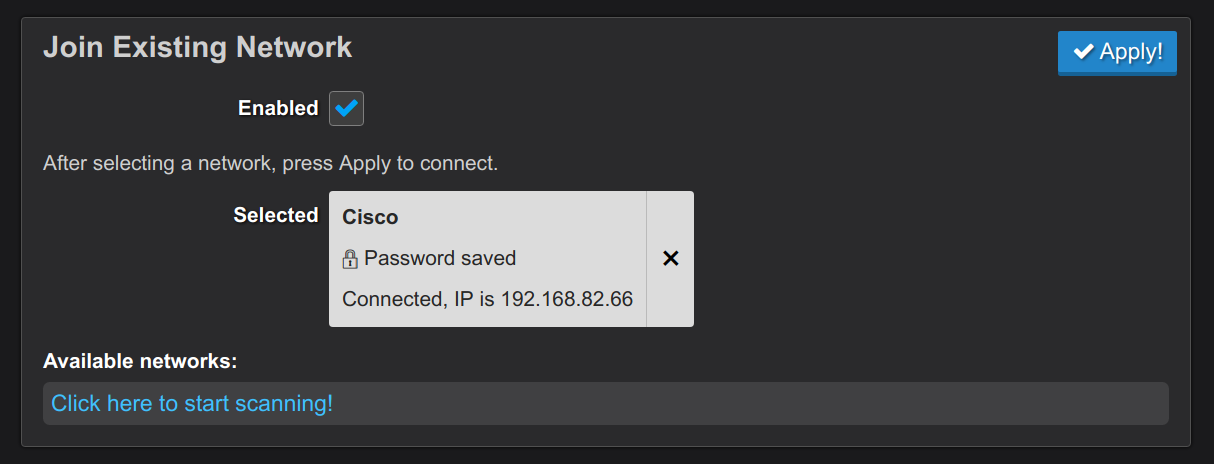
espterm can also be made to connect to your WiFi router and act as another station in your network. In this mode any computer in the network will be able to connect to it.

If connected to a WiFi router, espterm can also be assigned a static IP address.

Configure the ESP-01 serial port settings to match that of the ODROID C2’s serial console port.


If everything goes well you should now have a remote web console to your C2.

You can now safely change the network settings of your headless server without fear of losing connectivity!
Continuing with the theme of my last post, as you've have seen, scaling up is not the only way to get things done. We've managed to build a remote management solution using a $3 USD microcontroller module. Remote management is an old concept, but that also teaches us that: just because an idea is old doesn't mean it is not still useful  Happy hacking.

“Close-up of the keyboard of a an old typewriter” by Sergey Zolkin on Unsplash